Picade Improvements
| Zeile 1: | Zeile 1: | ||
| − | On this page I'll document my improvements on the Picade retro arcade cabinet for your Raspberry Pi. It is sold by [http://shop.pimoroni.com/products/picade Pimoroni] in UK. I want to improve it not because it isn't well designed, but because I don't like a few methods they used. |
+ | On this page I'll document my improvements on the Picade retro arcade cabinet for your Raspberry Pi. It is sold by [http://shop.pimoroni.com/products/picade Pimoroni] in UK. I wanted to improve it - not because it isn't well designed, but because I don't like a few methods they used. |
<div><ul> |
<div><ul> |
||
| Zeile 15: | Zeile 15: | ||
** the display and |
** the display and |
||
** the display controller. |
** the display controller. |
||
| − | * Pimoroni (as well as others) recommend a 2A 5V power supply to feed the Pi. The picade gets its juice from one of the USB ports from the Pi as well as the display controller. The controller feeds the display by its flat flex cable. |
+ | * Pimoroni (as well as others) recommend a 2A 5V power supply to feed the Pi. The Picade and the display controller get their juice from one of the USB ports of the Pi. The controller feeds the display by its flat flex cable. |
| − | * An average USB port can distribute 250mA to a connected device. After request it can have up to 500mA. |
+ | * Your average USB port can deliver 250mA to a connected device. Upon request it can have up to 500mA. |
** The picade pcb - especially the audio amplifier - is able to draw up to 0.6A. There is a [http://forums.pimoroni.com/t/audio-performance-awful/890 forum post] describing this behaviour. |
** The picade pcb - especially the audio amplifier - is able to draw up to 0.6A. There is a [http://forums.pimoroni.com/t/audio-performance-awful/890 forum post] describing this behaviour. |
||
** The Raspberry Pi can distribute up to 1.2A to a USB device, if you put a ''max_usb_current=1'' line into ''/boot/config.txt''. |
** The Raspberry Pi can distribute up to 1.2A to a USB device, if you put a ''max_usb_current=1'' line into ''/boot/config.txt''. |
||
** Unfortunately I don't have a datasheet where the power consumption of the display controller board is described. |
** Unfortunately I don't have a datasheet where the power consumption of the display controller board is described. |
||
| − | ** The display backlight draws 1.782W, the display panel 0.356W - that gives 0.4276A. |
+ | ** The display backlight draws 1.782W, the display panel 0.356W - at 5V, that amounts to 0.4276A. |
** In total we have now more than 1A. |
** In total we have now more than 1A. |
||
| − | ** There is not much room to add a USB-Wifi or a USB-Bluetooth device. I tried it and it ended with the screen going black all the time |
+ | ** There is not much room to add a USB-Wifi or a USB-Bluetooth device. I tried it and it ended up with the screen going black all the time. |
* I ordered a 4A 5V power supply. |
* I ordered a 4A 5V power supply. |
||
** This power supply will directly feed the display controller and the display. |
** This power supply will directly feed the display controller and the display. |
||
| Zeile 28: | Zeile 28: | ||
== Boot & Shutdown == |
== Boot & Shutdown == |
||
| − | As soon as you plug the power into the Raspberry Pi it will boot. Maybe there is not always a need to boot up when you plug the power in? Simply unplugging the cabinet from the power supply will sooner or later corrupt the filesystem on the MicroSD card. When this happens you are out of luck. You might be able to correct the error by starting a fsck & repair, you'll need a keyboard to do this. There is as well a chance that linux cannot boot anymore with the damaged SD card - then you're out. Yes, there is a shutdown option inside the Retropie menu. But there is a better way: |
+ | As soon as you plug the power into the Raspberry Pi it will boot. Maybe there is not always a need to boot up when you plug the power in? Simply unplugging the cabinet from the power supply will sooner or later corrupt the filesystem on the MicroSD card. When this happens you are out of luck. You might be able to correct the error by starting a fsck & repair, but you'll need a keyboard to do this. However, there is a good chance that linux won't be able to boot from the damaged SD card - then you're out. Yes, there is a shutdown option inside the Retropie menu. But there is a better way: |
* I'll use an On/Off Power Switch from [https://www.pi-supply.com/product/pi-supply-raspberry-pi-power-switch/ Pi Supply] |
* I'll use an On/Off Power Switch from [https://www.pi-supply.com/product/pi-supply-raspberry-pi-power-switch/ Pi Supply] |
||
** It has three buttons for On, Off and Soft Off. |
** It has three buttons for On, Off and Soft Off. |
||
** It has two connections to the Raspberry Pi GPIO pins. |
** It has two connections to the Raspberry Pi GPIO pins. |
||
| − | ** By pressing the Soft Off button it will signal the Pi to do a shutdown. After 2 minutes it will cut off the power. A python script is waiting all the time for the signal. The script is provided by Pi Supply. |
+ | ** By pressing the Soft Off button it will signal the Pi to do a shutdown. After 2 minutes it will cut off the power. A python script is constantly waiting for the signal. The script is provided by Pi Supply. |
** Plugging in the power will not boot the Pi. You need to press the On button to distribute the power to the Pi. |
** Plugging in the power will not boot the Pi. You need to press the On button to distribute the power to the Pi. |
||
** You are still able to use the menu option of the Retropie menu - after that you can use the Off button to cut off the power. |
** You are still able to use the menu option of the Retropie menu - after that you can use the Off button to cut off the power. |
||
== External Connectivity == |
== External Connectivity == |
||
| − | Maybe I would like to use the Ethernet port on the Pi. Or I want to connect a USB keyboard or gamepad. I could open the rear door, plug the cable in, route the cable through the gaps on the lower end of the door and close it. But, you guessed it, there is a better way: |
+ | Maybe I would like to use the Ethernet port on the Pi. Or I want to connect a USB keyboard or gamepad. I could open the rear door, plug the cable in, route the cable through the gaps on the lower end of the door and close it. But - you guessed it - there is a better way: |
* I'll use panel mount extension cables. |
* I'll use panel mount extension cables. |
||
| Zeile 44: | Zeile 44: | ||
** There are Ethernet and USB types available from Adafruit. |
** There are Ethernet and USB types available from Adafruit. |
||
| − | == The Glue In Between == |
+ | == Keeping It All Together == |
| − | [[Datei:Standoff (Mittel).jpg|400px|thumb|right|]][[Datei:Platte.png|400px|thumb|right|]]During the build I refused to use the included M2.5 nylon screws to screw the Pi on the back plate. Instead I used 4 M2.5 brass standoffs, 4 M2.5X12mm screws and 4 M2.5 nuts. I'll try the same (but with M3 standoffs) with the Display button panel. But what to do with the power buttons, the panel mount cables and the power connector? I don't use the included tactile switches from the Pi Power Switch - they are unusable in a fixed mounted cabinet. Instead I use 16mm panel mount pushbuttons. I could drill holes into the back, but I'll need to drill a greater diameter half through and a smaller one all through because the fixing threads on the power connector and the buttons have a height of only a few mm. The same goes with the Ethernet connector. It is not possible to unplug an Ethernet cable when you can't reach the spring tab to release it. I found a better way: |
+ | [[Datei:Standoff (Mittel).jpg|400px|thumb|right|]][[Datei:Platte.png|400px|thumb|right|]]During the build I refused to use the included M2.5 nylon screws to screw the Pi on the back plate. Instead I used 4 M2.5 brass standoffs, 4 M2.5X12mm screws and 4 M2.5 nuts. I'll try the same (but with M3 standoffs) with the Display button panel. But what to do with the power buttons, the panel mount cables and the power connector? I don't use the included tactile switches from the Pi Power Switch - they are unusable in a fixed mounted cabinet. Instead I use 16mm panel mount pushbuttons. I could drill holes into the back, but as the fixing threads on the power connector and the buttons are only a few mm high, I'd need to drill a biger diameter half way and a smaller one all the way through. The Ethernet connector has the same issue. It is not possible to unplug an Ethernet cable when you can't reach the spring tab to release it. I found a better way: |
* Since I own a 3D printer, I can print a small back plate. |
* Since I own a 3D printer, I can print a small back plate. |
||
Version vom 26. August 2015, 10:20 Uhr
On this page I'll document my improvements on the Picade retro arcade cabinet for your Raspberry Pi. It is sold by Pimoroni in UK. I wanted to improve it - not because it isn't well designed, but because I don't like a few methods they used.
Inhaltsverzeichnis |
The power distribution
- There are 4 modules which need power.
- The Raspberry Pi itself,
- the Picade PCB (with audio amplifier),
- the display and
- the display controller.
- Pimoroni (as well as others) recommend a 2A 5V power supply to feed the Pi. The Picade and the display controller get their juice from one of the USB ports of the Pi. The controller feeds the display by its flat flex cable.
- Your average USB port can deliver 250mA to a connected device. Upon request it can have up to 500mA.
- The picade pcb - especially the audio amplifier - is able to draw up to 0.6A. There is a forum post describing this behaviour.
- The Raspberry Pi can distribute up to 1.2A to a USB device, if you put a max_usb_current=1 line into /boot/config.txt.
- Unfortunately I don't have a datasheet where the power consumption of the display controller board is described.
- The display backlight draws 1.782W, the display panel 0.356W - at 5V, that amounts to 0.4276A.
- In total we have now more than 1A.
- There is not much room to add a USB-Wifi or a USB-Bluetooth device. I tried it and it ended up with the screen going black all the time.
- I ordered a 4A 5V power supply.
- This power supply will directly feed the display controller and the display.
- Since it comes with a coaxial power connector I'll mount the female part at the back of the cabinet to be able to unplug it.
Boot & Shutdown
As soon as you plug the power into the Raspberry Pi it will boot. Maybe there is not always a need to boot up when you plug the power in? Simply unplugging the cabinet from the power supply will sooner or later corrupt the filesystem on the MicroSD card. When this happens you are out of luck. You might be able to correct the error by starting a fsck & repair, but you'll need a keyboard to do this. However, there is a good chance that linux won't be able to boot from the damaged SD card - then you're out. Yes, there is a shutdown option inside the Retropie menu. But there is a better way:
- I'll use an On/Off Power Switch from Pi Supply
- It has three buttons for On, Off and Soft Off.
- It has two connections to the Raspberry Pi GPIO pins.
- By pressing the Soft Off button it will signal the Pi to do a shutdown. After 2 minutes it will cut off the power. A python script is constantly waiting for the signal. The script is provided by Pi Supply.
- Plugging in the power will not boot the Pi. You need to press the On button to distribute the power to the Pi.
- You are still able to use the menu option of the Retropie menu - after that you can use the Off button to cut off the power.
External Connectivity
Maybe I would like to use the Ethernet port on the Pi. Or I want to connect a USB keyboard or gamepad. I could open the rear door, plug the cable in, route the cable through the gaps on the lower end of the door and close it. But - you guessed it - there is a better way:
- I'll use panel mount extension cables.
- Their cables have a length of 22cm - enough to reach the ports on the Pi.
- There are Ethernet and USB types available from Adafruit.
Keeping It All Together
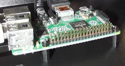
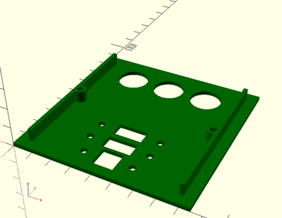
During the build I refused to use the included M2.5 nylon screws to screw the Pi on the back plate. Instead I used 4 M2.5 brass standoffs, 4 M2.5X12mm screws and 4 M2.5 nuts. I'll try the same (but with M3 standoffs) with the Display button panel. But what to do with the power buttons, the panel mount cables and the power connector? I don't use the included tactile switches from the Pi Power Switch - they are unusable in a fixed mounted cabinet. Instead I use 16mm panel mount pushbuttons. I could drill holes into the back, but as the fixing threads on the power connector and the buttons are only a few mm high, I'd need to drill a biger diameter half way and a smaller one all the way through. The Ethernet connector has the same issue. It is not possible to unplug an Ethernet cable when you can't reach the spring tab to release it. I found a better way:- Since I own a 3D printer, I can print a small back plate.
- It will hold all the buttons and connectors.
- It will be about 2mm thick and a 85mm by 85mm square.
- I can screw it into a 80x80 square break out near the Pi mounting place.
- Most of the square break is already done. You only need to remove a small corner and the air grill parts.
- Since the plate is bigger than the cut out, you need not to be very accurate with your cuts.
I'll provide you with the .stl file after I finished my Picade improvements.
Configuration Changes
- add to /boot/config.txt
- max_usb_current=1 # give up to 1.2A to USB devices (newer firmware)
- safe_mode_gpio=4 # give up to 1.2A to USB devices (older firmware)
- disable_audio_dither=1 # remove static noise from speakers
Bill of Material
- 4 M2.5 standoffs
- 4 M2.5x12mm screws
- Raspberry Pi On/Off Power Switch
- 3 16mm Panel Mount Momentary Pushbutton (red, yellow, green)
- 2 Panel Mount USB Cable - A Male to A Female
- Panel Mount Ethernet Extension Cable
- 3D printed back plate
